This article contains edited details of the NBSC format. These are reproduced with some corrections from a posting to the NBTVA forums.
Disclaimer: The information presented here is intended to be a brief introduction to the NTSC standard and its workings and how it can be applied to narrow bandwidth television. I'm no authority on NTSC so don't rely too heavily on facts presented here!
The aim of this experiment has been to see if it is possible to transmit full colour NBTV pictures in a single analogue sound channel. The aims were:
After some basic experimentation (in software only) it was decided to use a simple NTSC like colour encoding scheme with some simplifications and alterations to suit the narrow bandwidth of NBTV.
Systems such as PAL and SECAM were avoided because they require delay lines to function correctly and their advantages
rely on aspects of the picture geometry and timing that are not that applicable in NBTV (for instance PAL's automatic
hue correction produces very noticeable hanover bars due to NBTV's low resolution).
[Note: Further experimentation needs to be performed to verify the above statements, it is now the opinion of the author
that both PAL and SECAM could be operated satisfactorily should some means of providing a 2.5ms delay be found.]
There have been many attempts at producing colour television over the years, and it is beyond the scope of this article to go into the pros, cons, politics and comparative theology of the various competing analogue and digital colour systems – the author just picked the one he understood most readily and stuck to it!
Most colour systems have had to try and be "compatible" with existing systems. That is they have had to introduce the extra signals required to reproduce colour into the same signal as an existing Black & White service without upsetting existing receivers.
NTSC is the American system invented in 1953 that does just that. To acheive this it seperates out the three primary colours and then mathematically rearranges them (see next section) in such a way as to have a set of three primaries one of which is the original Black and White signal.
The two extra components are then Modulated onto a sub carrier and shoe horned in to (see 4. Modulating the colour difference signals) the existing Black and White video spectrum.
The human eye contains two types of cells for detecting colour, rods and cones. Rods are sensitive to a wide range of
colours and are more sensitive than cones - effectively giving is black and white only vision when it is dark. The
cones come in three varieties that sense red green and blue light. This is why there are three primary colours.
So to make a television picture that looks like full colour we need to present our eyes with three separate red,
green and blue signals at the same time, which can vary independently.
[Note: Some recent research
has shown that some women can actually see four distinct colours (with an extra "orange" receptor).]
However, we don’t have room for all these extra signals – remember we want to keep the black and white signal AND fit everything in the same bandwidth! So, a method needs to be found to reduce this number of signals if possible. One way to do this is to send three signals:
        Y = R + G + B
        U = B – Y
        V = R – Y
Here Y is the original black and white signal which is an admixture of the red, green and blue signals. U is the difference between the blue signal and the Y signal, and V is the difference between the Red and the Y signal. These signals are mixed together at the camera end and at the receiver end , if the receiver is black and white then only the Y signal need be recovered. However if the receiver is colour then some simple addition and subtraction can be performed to recover the RGB signals:
        R = Y + V
        = Y + (R – Y)
        = R
        B = Y + U
        = Y + (B – Y)
        = B
        G = -(U + V + Y)
        = Y – B + Y – R – Y
        = Y – B – R
        = R + G + B – B – R
        = G
In the real world a black and white signal is not made of red, green and blue signals in equal proportions as the eye has a different sensitivity to each of the colours so a different set of proportions is actually used (however the sums still work similarly), see the Wikipedia article on YUV for more information.
For completeness sake here are the actual transformations that are used in the NTSC and NBSC to map from R,G,B to YUV:
        Y = 0.299 * R + 0.587 * G + 0.114 * B
        U = -0.14713 * R + 0.28886 * G + 0.436 * B
        V = 0.615 * R -0.51499 * G - 0.10001 * B
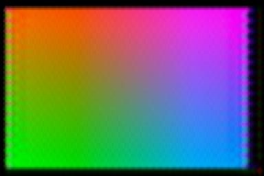
The image above shows the colours given when we make a map of U and V onto a two dimensional plane. The horizontal axis represents U going from -0.5 to +0.5, the vertical axis V going from -0.5 (bottom) to +0.5 (top). At all points Y is 0.5. It should be noted that the colours at the very edges of the map will not display correctly on an RGB monitor as they actually produce colours that are outside the range of the monitor.
In the NTSC scheme two slightly different signals I and Q are used when the signals are created, they are not exactly related to red and blue but instead to slightly different colours to which the eye is more sensitive – see the Wikipedia article on YIQ. However, most television receivers use YUV when decoding the signal as the circuitry is simpler.
        Y = 0.299 * R + 0.587 * G + 0.114 * B
        I = 0.595716 * R - 0.274453 * G - 0.321263 * B
        Q = 0.211456 * R - 0.522591 * G + 0.311135 * B
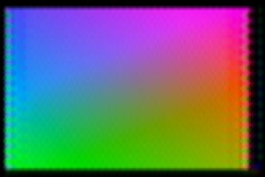
The image above shows the I-Q Map.
When encoding signals in NTSC if the I and Q vectors are used it is possible to perform some trickery that allows the sub-carrier to be placed at near the top of the available bandwidth without losing too much colour information. The Q signal (to which the eye is least sensitive) is double-sideband modulated with a small bandwidth, the I signal is modulated with a wider bandwidth but the part of one sideband is truncated. Without special measures this leads to cross-talk between the two signals. Some experimentation with the playback software will show this. The encoding software always uses I and Q vectors though only the Formats marked "C filtered" perform the removal of the higher I sideband. The playback software can be set to decode either using I/Q or U/V (in which case equal filtering of U and V channels is performed).
After seperation into Y (luminance) and U,V or I,Q (colour components), we still have three separate signals that need to be fitted into the same space as the original black and white signal AND still be understood by an existing black and white receiver. The Y signal is identical to the original Black & White signal so now we need to find a way of shoehorning the other two signals into the same bandwidth...
To accommodate the existing black and white receivers the Y signal (along with the usual sync pulses etc) is transmitted as normal – this on a black and white receiver gives a nice black and white picture. Now what to do with the U & V (or I & Q) signals. What was decided in the NTSC (and PAL) systems was to use Quadrature Amplitude modulation. This very grand title in fact describes a very nice neat and simple (if difficult to describe!) system.
In Amplitude Modulation a carrier signal, at a high frequency is modulated (made large or smaller in sympathy with) by a lower frequency signal, such as sound.
In quadrature modulation two separate carriers are used, both at the same frequency but at a phase difference of 90 degrees. Each of these is modulated by the U or V signal in such a way that when the U or V signal is zero the output is also zero and if the U or V signal is negative then the carrier is modulated “upside down”.
Because the carriers are sine waves and the two signals are out of phase by 90 degrees when one carrier is at its maximum or minimum the other is at zero. So, if the two carriers are modulated and added together the original modulating signals can still be retrieved by sampling the signal when each of the carriers would be at its maximum or minimum, as the other carrier would be zero at that point hence no information would be present for the other signal.
This signal is called the Chroma, Chrominance or C signal.
The signals can also be recovered by multiplying the signal by a square wave or sine wave that is in sympathy with the original carrier, because a sine wave averages out to zero over a full wave, if this recovering wave is at the same phase as the carrier then the signal will be recovered (averaged over a cycle) whereas the other signal being 90 degrees out of phase will not.
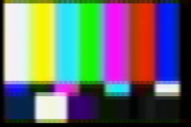
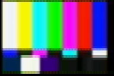
The image above shows what happens when a signal comprising a black, grey, white, red, green, blue colour sequence is transmitted.
The bottom trace shows the actual colour to be transmitted, the Red, Green and Blue components show the intensity of red, green and blue in each colour. The Y, U and V traces show these signals rearranged into our three Y, U and V signals.
The next two traces show the in-phase and quadrature carriers, i.e. the carrier and the 90 degrees out of phase carrier, the signals above show these two carriers modulated independently with then U and V signals and then the QAM modulated signal (Chroma) shows these signals added together.
Superimposed on the colours at the bottom is a trace of the actual signal that would be transmitted, this is simply the Y signal with the QAM signal added. On a black and white receiver this will look like a normal picture with the colour parts looking like a light grey with a patterning superimposed - produced by the QAM signal.
The decoding process is shown in the top four traces. At the colour receiver the Chroma signal can be separated from the Y signal by using high and low-pass filters or notch and band-pass filters.
A pair of square waves (that’s how it works in this simple receiver in analogue NTSC receivers usually sine waves would be used) is generated in sympathy with the original in-phase and quadrature carriers. These square waves are then multiplied against the extracted Chroma signal to give the top two traces, if these are low-pass filtered to average the signal out over a full wave of the carrier (pink-superimposed traces) then a signal similar to (but of diminished quality to) the original U and V signals can be obtained.
Once the U and V signals and the filtered Y signal are available they can then be added together (as per the formulas above) to re-create the original R, G and B signals.
There are some problems with the NTSC scheme though:
The Chroma signal superimposed upon the Y signal appears as a patterning on black and white receivers, this must either be lived with or filtered out. On most Nipkow disc receivers the size of the apertures effectively filters most of this patterning out, but some is still apparent.
To reduce the impact of patterning there are various “dodges” that can be used when choosing the sub-carrier frequency. One is that the frequency should be an odd multiple of half the line frequency. If this is done the patterns are opposite in phase on each line and so a stationary “checkerboard” pattern is produced. Also this choice of frequency means that the parts of the spectrum used by the colour signal tend to interleave with those used by the luminance signal - this is beyond the scope of this article. For more information it is recommend to get hold of "Colour Television" by Carnt & Townsend pub. Iliffe 1961 for a full explanation.
Another dodge is to also add a small increment to the frequency that is half the frame rate, this then makes each frame have a pattern that is opposite to the last. On black and white receivers, if the frame rate is high enough they will cancel each other out and disappear. Unfortunately we cannot use this dodge on NBTV because the frame rate is quite low and this just produces a very annoying checker board pattern that flashes quite alarmingly!
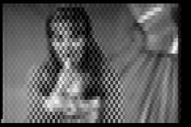
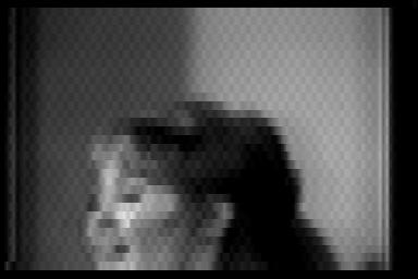
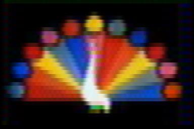
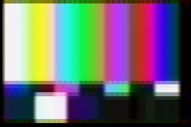
The pictures show above the effect of colour patterning. At the top a colour picture is played on a B&W "receiver" with a full 20kHz bandwidth. As can be seen the patterning is quite severe and distracting. In the second picture a notch filter has been introduced which filters out frequencies around the sub-carrier frequency - large areas of colour patterning are reduced in amplitude, though there is still noise at edges. The third picture shows that for practical purposes when using a Nipkow disc receiver the effects of dot-structure are more or less eliminated by the bandwidth limiting features of the large round holes.
To improve dot-structure the amplitude of the colour signals can be reduced, however this leads to a marked worsening of signal to noise ration and cross-colour (see below) so a compromise must be struck. After much experimentation, I have stuck to the original NTSC spec!
The U and V signals used to modulate the colour subcarrier must have a much lower bandwidth than the carrier frequency (in this system the U and V signals are filtered to 2.5kHz for a 15kHz subcarrier). This is not as drastic as it might seem. The eye and brain are more sensitive to fast changing black and white signals and are forgiving if the colour signal is a little “smudged” for this reason the low colour bandwidths are not the end of the world but any improvement would be worthwhile.
NTSC, as mentioned before, uses I and Q signals that are slightly different to the simple U & V signals described in this article. This is so that a wider bandwidth can be placed on the orange-cyan colours (to which eye / brain is more sensitive). To take full advantage of this receivers need to be slightly more complex in design and so have been skipped in this first attempt.
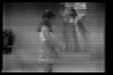
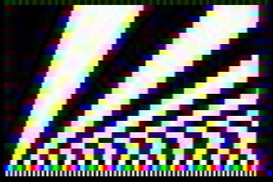
The pictures above show the effects of filtering. In the top picture the I and Q components have been low pass filtered before being modulated to limit the amount of sideband cross talk distortion before being low pass filtered to 16kHz. The final picture shows the effects of the final chrominance filtering - now the I signal is partly single sideband and there is some cross talk between the I and Q channels. (Notice the green-cyan transition is particularly affected, this is also noticeable on regular NTSC broadcasts of colour bars, where green and cyan look almost grey to those more used to PAL or SECAM).
The good news is that for most NBTV purposes (i.e. recording to / playing back from CD or computer) unfiltered (or IQ filtered) colour signals can be used with little effect on the Black and White picture.
This is where there are signals contained in the Y signal which can are at the same frequency as the sub-carrier. These signals get picked up by the filter that extracts the Chroma signal and confuse the U and V demodulators and tend to appear as speckles or at the edges of sharp transitions of light to dark. This is especially noticeable at the right hand edge of pictures produced by this receiver where the high-frequency components of the sync-pulse give rise to a constant pattern.
The dodge to get round this is to filter any signals near the subcarrier frequency out of the Y signal using a notch filter. However any filtering tends to mar the quality of the original Y signal.
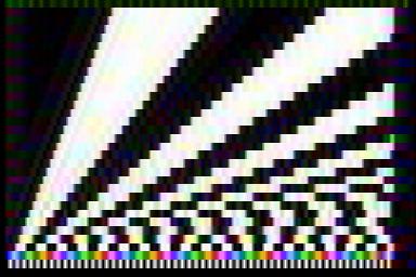
The pictures above show the effects of cross-colour (the sparkly bits shouldn't be there). In the top filter the Moiré pattern has been captured with no filtering of the luminance signal. Because the Black & White picture has many high frequency components some of these are at or near the sub-carrier frequency meaning that the decoders cannot distinguish them from real colour signals.
In the second picture the luminance signal has been notch filtered to remove components at the sub-carrier frequency before combining with the colour signals. As can be seen this has drastically reduced the sparkly cross-colour at the expense of a slightly blurred Black and White picture. There is still some cross-colour on the second to last line (which contains a 12kHz pattern) which is just outside the notch-filter's range.
One item mentioned above that was brushed over, was how the receiver makes a copy of the original in-phase and quadrature carriers. This is one of the more tricky aspects of the NTSC system: not only must the subcarriers at the receiver be of the same frequency but also of exactly the same phase. With the use of quartz crystals we can ensure very accurate matching of frequencies at the transmitter and receiver but we also need some way of maintaining our carriers in phase.
To achieve synchronisation, a system known as “colour burst” is used. In this at well defined times during the transmitted signal a burst of colour is transmitted of a known (0 degree) phase and amplitude: i.e. a burst of the in-phase carrier signal. This signal can then be compared with the local carriers and if they are out of phase they can be adjusted as necessary.
In the receiver described later this is achieved by slightly speeding up or slowing down the master oscillator depending on whether the demodulated V signal is positive or negative during the colour burst – as the V signal is 90 degrees out of phase if the master oscillator is correct then the V signal should be zero when the colour burst is being demodulated if the phase is “perfect”.
In normal NTSC signals this colour burst occurs at the start of each line for 10 cycles – however there isn’t room for this in the NBTV signal so instead the colour burst happens once per frame, taking up the whole of the first line.
Older NTSC receivers suffered from all sorts of problems caused by the local subcarrier oscillator being slightly out of phase with the transmitter (caused by all sorts of reasons). For this reason older sets are fitted with a “hue” or "tint" control which can be used to manually adjust the matching up of the colour burst with the local oscillator. As this hue control is adjusted the phases of the subcarriers are changed with respect to the colour burst slightly and this gives an effect where the colours all change slightly from where they should be – as if the U-V or I-Q map included above had been rotated about its centre.
For this reason NTSC (which actually stands for “National Television System Committee”) is often know as “Never Twice the Same Colour”, as
the user needed to manually adjust the hue control to get the right colours. Modern sets (and other colour standards such as PAL and SECAM)
have come up with various other “dodges” to either hide or correct the problems. In the simple receiver and standard presented here a Hue
control is used!
[Note: The author can confirm however that after a recent trip to Cuba the hue problem has not been cured everywhere - the local baseball games
needed frequent adjustment, with the hue error often fluctuating wildly due to poor transmission links.]
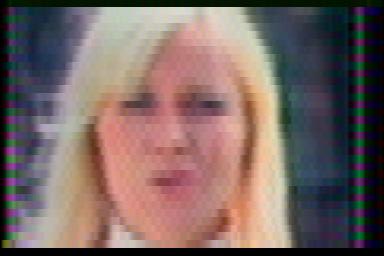
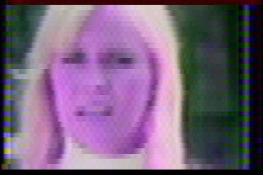
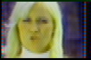
The pictures above show the affects of incorrect hue setting on felsh tones.
A simplified version of NTSC was chosen with the following parameters and changes from specification:
      Subcarrier Frequency: 15,000Hz
      Modulation: QAM I&Q with supressed carrier
      I bandwidth: (<2.5kHz)
      Q bandwidth: (<1kHz)
      Colour burst: Whole of first line after missing sync
      15% modulated at black level
      (i.e. no NTSC pedestal)
      Line sync width: 0.1333333ms (to reduce cross-colour)
Note: The colour burst may be reduced to only the second half of the first line - leaving the rest of the line free for teletext etc.
 NBSC
NBSC